Electricity:
Electricity is convenient form of energy for a variety of uses in schools, hospitals industries and so on.
Electric current:
Electric charges flow through a conductor , then there is an electric current in the conductor.
Electrical circuit:
A continuous and closed path of an electric current is called an electric circuit.

Electric current:
Electric current is expressed by the amount of charge flowing through a particular area in unit time.
It is the rate of flow of electric charges.
If net charge Q flows across any cross section of a conductor in time t, then the current I, through cross section
I= Q/t
SI unit of electric charge is coulomb.
1 coulomb= charges contained in nearly 6×10⁸ electrons
SI unit of electric current is Ampere (A)
1 A= 1C/1s
One ampere is constituted by the flow of one coulomb of charges per sec.
Small units of electric current
1mA= 10-3A
1µA=10-6A
Instrument used to measure current in a circuit is Ammeter.
Ammeter is always connected in series in the circuit through which the current is to be measured.
When phenomenon of electricity was first observed, electrons were not known. So electric current was considered to be the flow of positive charges and the direction of flow of positive charges was taken to be direction of electric current.
Conventionally, in an electric circuit, the direction of electric current is taken as opposite to the direction of the flow of electrons.
Electric potential and potential difference
Electrons move only if there is a difference of electric pressure – called the potential difference along the conductor.
This difference of potential may be produced by a battery consisting of one or more electric cells. The chemical action within cell generates the potential difference across the terminals of the cell, even when no current is drawn from it. When the cell is connected to the conducting circuit element, the potential difference sets the charges in motion in the conductor, and produces an electric current. In order to maintain current in given electric circuit, the cell has to expend its chemical energy stored in it. Electric potential difference between two points in an electric circuit carrying some current as the work done to move a unit charge from one point to the other.
Potential difference (V) between two point= work done (W) / Charge (Q)
V=W / Q
SI unit of electric potential difference is volt(v).
One volt is the potential difference between two points, in a current carrying conductor, when 1 joule of work done to move a charge of 1 coulomb from one point to another.
1 volt= 1 joule / 1 coulomb
1v – 1 JC-1
Potential difference is measured by means of instrument called voltmeter. It is connected in parallel across the points between which potential difference is to be measured.
Circuit diagram
Schematic diagram in which different components of the circuit are represented by the symbols which are conveniently used.

Ohm’s Law
The potential difference V , across the ends of a given metallic wire in an electric circuit is directly proportional to the current flowing through it, provided its temperature remains the same.
V α I
V / I = R (constant)
V= I R
R-> is a constant for a given metallic wire at a given temperature and is called resistance.
It is the property of a conductor to resist the flow of charges through it.
SI unit of resistance is Ohm (W)
If the potential difference across the two ends of a conductor is 1 V and the current through it is 1A, then the resistance R of the conductor is 1 W.
1 ohm = 1 volt/ 1 ampere
A component used to regulate current without changing the voltage source is called variable resistance.
In an electric circuit a device called rheostat is used to change the resistance in the circuit.
- A component of a given size that offers a low resistance in an electrical circuit is known as a good conductor.
- A conductor having some appreciable resistance is called resistor.
- A component of identical size that offers a higher resistance is a poor conductor.
- An insulator of the same size offers even higher resistance.
Factors on which resistance of a conductor depend:
Resistance of a uniform metallic conductor is directly proportional to its length (l)and inversely proportional to the area of cross section (A) area of cross section.
R α l
R α 1/ A
R α l/ A
R=ρ l/ A
Ρ is constant of proportionality and it is called as electrical resistivity of the material of the conductor.
SI unit of resistivity is Wm
- Metals and alloys have low resistivity (range 10-8 Wm to 10-6 Wm)
- Rubber, plastic –insulators have high resistivity (range 1012Wm to 1017Wm)
Resistivity and resistance vary with temperature.
Though resistivity of an alloy is higher than that of its constituent metals, alloys do not oxidize readily at high temperature. So alloys are used in electrical heating devices.
Resistance of system of resistance:
There are two methods of joining resistors together.
Resistors in series
The resistors joined end to end,are said to be in series in the electric circuit.

In the circuit the potential difference(V) is equal to the sum of the potential difference of the resistors connected in series.(V1,V2,V3)
V= V1+V2+V3 ——–eqn 1
Let the current in the circuit be I and the equivalent resistance , of the resistors connected in series be R.
By Ohm’s law
V=IR
On applying Ohm’s to the three resistors separately,
V1= IR1
V2= IR2
V3= IR3
From eqn 1,
IR= IR1 + IR2 + IR3
R= R1 + R2 + R3
When several resistors are connected in series, the resistance of the combination R is equal to the sum of individual resistances.
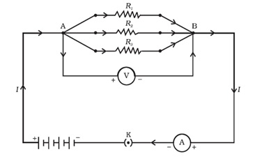
Resistors in parallel:
The resistors are connected together between two end point , then the resistors are said to be in parallel.

In case the resistors are connected in parallel the potential difference across the resistors is same, ie V.
Electric current in the circuit (I) is sum of the separate current through each resistors (I1,I2,I3)
Let RP be the equivalent resistance of parallel combination of resistors
By Ohm’s law
I = V/RP
Applying Ohm’s law to each resistor
I1 = V/R1
I2 = V/R2
I3 = V/R3
I =I1+I2 + I3
V/RP= V/R1 + V/R2 + V/R3
1/RP= 1/R1 + 1/R2 + 1/R3
So, reciprocal of equivalent resistance of the group of resistors connected in parallel is equal to the sum of the reciprocals of the individual resistances.
Disadvantages of connecting home appliances in series:
- The current through all the resistors are same when the resistors are connected in series. The home appliances need different values of current.
- When appliances are connected in series, if one component fails, the circuit is broken and none of the components works.
Heating effect of electric current:
The battery or a cell connected to the electric circuit maintains the current in the circuit by expending energy. A part of the source energy in maintaining the current may be consumed in doing work, like rotating blades of an electric fan. Rest of the energy will converted to heat and raise the temperature of the gadget.
If the electric circuit is purely resistive, that is the configuration of resistors only connected to the battery, the source energy continually gets dissipated entirely in the form of heat. This is known as heating effect of electric current. This effect is utilised in devices such as an electric heater, electric iron etc.
Consider current I flowing through a resistor of resistance R.
Let the potential difference be V and t be the time during which the charge Q flows across.
Work done= VQ
P= Work done / t
= VQ/t
P=VI
Energy supplied = Power X time
=P X t
=VIt
=I2Rt……V=IR
Amount of heat produced in time t is
H=I2RT
This is known as Joules’ law o heating.
The law states that, the heat produced in the resistor is i) directly proportional to the square of the current for the given circuit, ii) directly proportional to the time for which the current flows in the circuit.
Practical applications of heating effect o electric current
- In heating appliances like electric toaster, laundry iron, electric kettle etc
- Electric heating is also used to produce light, as in electric bulb.
- Fuse used in electric circuit.
Electric power:
Power= VI
P= I2R= V2/R
The SI unit of electric power is watt(W).
1 watt is the power consumed by a device that carries 1 A of current when operated at potential difference of 1 V.
The unit of electric energy is ,watt hour(W h). One watt hour is the energy consumed when one Watt of power is used for one hour.
Commercial unit of electric energy is kilowatthour, and it is commonly known as unit.
1kWh= 1000 watt X 3600 second
=3.6 X 10⁶ watt second
=3.6 X 10⁶ joule (J)
You can download the notes from here.